Laser welding can produce a clean, narrow seam, yet small process changes can leave visible and costly flaws. A dull or misaligned focus, for example, may cause uneven penetration. Excessive heat can widen the weld pool, while poor shielding may leave pores or oxidation. These problems rarely have just one cause. They often arise from a combination of material condition, joint fit-up, beam settings, and operator practice.
For a practical perspective, laser-processing specialist Dr. John Powell’s work highlights the importance of controlling the interaction between the beam and the material. A useful summary is: “Consistent weld quality depends on controlling the process, not just increasing power.” This is a paraphrase, not a verified verbatim quotation. It points to a common mistake: raising power to fix a weak seam can create spatter, burn-through, or distortion instead.
So, how to reduce defects in laser welding? Start with observable checks: clean the joint, confirm the gap, inspect the optics, and verify focus before production. Then record the settings and examine sample welds for penetration, porosity, and surface irregularities. Small checks matter. Even with a stable setup, results can shift when material thickness or fit changes. No checklist removes every risk, and that deserves attention. This guide explores why defects happen and how careful setup, monitoring, and adjustment can reduce them without treating one machine setting as a universal fix.
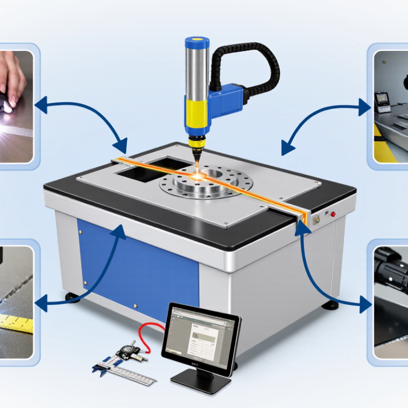
Laser welding defects are unwanted changes in or around the fused joint. Common examples include porosity, undercut, cracks, incomplete penetration, and excessive spatter. A porous weld may show tiny round voids in a cut cross-section. Undercut looks like a narrow groove along the weld toe. Some flaws are hidden beneath a clean surface.
These defects affect weld quality in different ways. Porosity and incomplete fusion reduce the effective load-bearing area. A crack can grow under vibration or repeated heating. Undercut concentrates stress at the joint edge, while excess spatter can signal unstable energy delivery or poor fit-up. Appearance alone is not enough. A bright, even bead does not prove sound internal bonding. Inspection should match the part’s material, thickness, and service demands. Diagnosis can be messy: several causes may produce similar marks, so changing settings blindly can make matters worse.
Tips: Clean oil, oxide, and moisture from the joint. Check focus, fit-up, shielding gas flow, and laser power in small, controlled steps. Keep a sample weld for comparison. If a defect persists, section or test the joint rather than guessing.
Laser-welded joints can look clean while hiding serious defects beneath the surface. Common problems include porosity, lack of fusion, undercut, cracks, spatter, and excessive penetration. Porosity appears as small gas cavities, often revealed by radiographic or ultrasonic testing. Contaminated surfaces, moisture, unstable shielding gas, or excessive welding speed can cause it. Clean metal matters.
Lack of fusion leaves parts of the joint unwelded. It may result from poor beam alignment, insufficient energy, or an incorrect focal position. Undercut forms as a narrow groove beside the weld bead when heat input or travel speed is poorly controlled. Cracks are more dangerous, especially near rigid joints and heat-sensitive alloys. Preheating, controlled cooling, and suitable joint design can reduce stress, but they cannot repair poor preparation. Spatter and excessive penetration may indicate excessive power or an unstable keyhole.
Practical control starts before welding. Check fit-up, gap size, surface cleanliness, and shielding flow. Use a qualified procedure, then verify bead shape through macro-section tests and non-destructive inspection. Small parameter trials are safer than changing several settings together. I have seen operators blame the laser when a fixture shift caused incomplete fusion. That mistake is easy to repeat. Record power, speed, focus position, gas flow, and inspection findings for each batch. A visually attractive weld is not proof of a sound joint.
Laser welding defects often begin before the beam reaches the joint. A narrow fit-up gap can let the keyhole wobble, trapping gas as the molten pool closes. Oil, oxide, and moisture add another source of porosity. Small gaps matter. Material thickness and joint design also shape heat flow: reflective aluminum, for example, can absorb less laser energy than steel, while a sudden change in thickness may create uneven penetration.
Process settings interact, not act alone. Excessive speed can leave incomplete fusion; too much power or an unstable keyhole can increase spatter and porosity. Shielding gas coverage, focus position, and clamping pressure deserve checks alongside power and travel speed. A useful reference is ISO 6520-1:2007, which classifies welding imperfections into six main groups, including cracks, cavities, and lack of fusion. That range is a reminder: one defect label may hide several different causes.
Material and process records help narrow the search. Track alloy, surface condition, joint gap, focus, power, and travel speed for each trial. Then inspect a cross-section, not just the shiny bead. ISO 13919-1:2019 defines three quality levels—B, C, and D—for imperfections in laser and electron-beam welded joints; the applicable acceptance level depends on the component and specification. A clean-looking seam is not proof of sound penetration. Nor is a single successful coupon. Real production varies, and that is where the process window can prove narrower than expected.
Laser welding defects often begin with small process changes. A dirty joint can create pores, unstable penetration, or surface spatter. Poor fit-up may leave gaps that the laser cannot bridge consistently. Excessive travel speed can cause lack of fusion, while excessive power may produce undercut or burn-through. Process control must connect laser power, travel speed, focus position, beam shape, and shielding gas flow. These settings should be verified on actual material, not copied blindly from a parameter sheet.
Equipment control is equally important. Check lens cleanliness, nozzle alignment, gas flow, and cooling performance before production. A loose fixture can shift the joint by only a fraction of a millimeter, yet the weld may change visibly. Use inspection samples and record key results, including bead width, penetration depth, and surface appearance. In practical trials, operators sometimes adjust power to hide a poor fit-up. That may solve one weld, but it creates an unstable process.
Tips: Clean both surfaces before welding. Confirm joint gaps with a gauge. Calibrate sensors regularly. Watch the first weld of every batch. Keep a simple defect log, even when the cause seems obvious. Short records reveal patterns. Do not ignore occasional defects; they may signal gradual lens contamination, fixture wear, or unstable gas delivery. Parameters should be reviewed after material changes, maintenance, or repeated quality variation. Perfect control is difficult. Careful feedback makes it more reliable.
A clean-looking laser weld is not necessarily sound. A bright bead may hide pores, incomplete fusion, or a narrow crack beneath the surface. Start with visual inspection under consistent lighting. Check the seam edges for undercut, spatter, discoloration, and changes in width. Use a magnifier when details are small. Keep the part and inspection area clean; residue can disguise surface openings.
Different methods reveal different defects. Dye penetrant testing can find flaws open to the surface, but it cannot show hidden porosity. Radiography can reveal internal voids, while ultrasonic testing may be difficult on thin parts or very narrow welds. Choose the method for the material, joint shape, and likely flaw—not convenience alone. That choice is not always obvious.
Evaluation should compare findings with documented acceptance criteria, including defect size, location, and frequency. For deeper investigation, cut a sample across the weld and examine its polished cross-section for penetration and fusion. Record the inspection method, equipment settings, and exact defect location so results can be compared across production runs. No single test catches everything. A missed flaw is still possible, so combine methods when the part’s risk and geometry warrant it.
| Defect | Typical causes | Detection methods | Evaluation considerations | Practical reduction methods |
|---|---|---|---|---|
| Porosity | Surface contamination, moisture, unstable keyhole formation, trapped shielding gas, or gases released from the material during solidification. | Radiographic testing (RT) can reveal internal pores; visual testing (VT) may identify surface openings. Metallographic sections help assess pore size and distribution during process qualification. | Record pore size, number, distribution, and location. Acceptance limits depend on the applicable product specification, joint design, and required service performance. | Clean and dry joint surfaces; control fit-up and shielding-gas coverage; use stable laser power and travel speed; verify focus position and material condition. |
| Lack of fusion | Insufficient energy at the joint, excessive travel speed, beam misalignment, incorrect focus, poor joint fit-up, or an unsuitable welding angle. | VT can identify visible discontinuities. RT, ultrasonic testing (UT), or destructive macrosectioning may be used depending on material thickness, joint geometry, and inspection requirements. | Check the length and location of unfused regions and whether they occur at the root, sidewall, or between passes. Method capability depends on joint geometry and defect orientation. | Align the beam with the joint; maintain consistent gap and clamping; qualify power, speed, focus, and beam angle; use seam tracking where joint-position variation is expected. |
| Cracking | Solidification or liquation behavior, high restraint, unsuitable material condition, rapid thermal gradients, or hydrogen and contamination in susceptible materials. | VT may find surface-breaking cracks. Liquid penetrant testing (PT) is suitable for accessible nonporous surfaces; magnetic-particle testing (MT) may be used on ferromagnetic materials. RT, UT, or metallography may be selected for internal assessment. | Determine crack location, orientation, length, and whether it is surface-breaking or internal. Cracks are generally treated as significant discontinuities; disposition must follow the governing code or specification. | Control joint restraint and thermal input; select compatible material and filler where applicable; remove contaminants; follow qualified preheat or interpass controls when required by the material procedure. |
| Undercut or underfill | Excessive travel speed or power, incorrect beam placement, poor edge preparation, or an unbalanced combination of heat input and material flow. | VT is commonly used to inspect the weld profile. A weld gauge, profile measurement, or cross-section can quantify groove depth and weld-face geometry. | Measure the depth and length of undercut and the weld-face profile. Compare measurements with the drawing and applicable acceptance criteria rather than using a universal limit. | Optimize power and travel speed; position the beam correctly; improve edge preparation and fit-up; stabilize the workpiece and verify the programmed weld path. |
| Excessive penetration or burn-through | Excessive energy input, slow travel speed, an oversized root gap, thin material, or inconsistent joint support. | VT can identify visible root protrusion or holes. RT and macrosectioning can assess internal penetration and root geometry where required. | Check penetration depth, root reinforcement, and any loss of material continuity. Evaluate against the specified joint profile and service requirements. | Reduce or stabilize energy input; increase travel speed where appropriate; control root gap and backing support; monitor material thickness and joint alignment. |
| Spatter and surface deposits | Unstable keyhole behavior, contamination, unsuitable process parameters, poor shielding, or excessive energy density for the joint conditions. | VT can assess the amount and location of adhered particles. Process monitoring can help correlate spatter events with changes in power, speed, or shielding conditions. | Assess whether spatter affects cleanliness, fit, coating, appearance, or downstream assembly. Distinguish loose particles from firmly attached material or surface damage. | Clean the joint; optimize power, speed, and focus; maintain nozzle condition and shielding coverage; use stable fixturing and consistent material presentation. |
| Weld misalignment or seam deviation | Inaccurate fixturing, part variation, joint movement, incorrect robot path, or inadequate seam-position sensing. | VT and dimensional inspection can check weld location. Laser seam-tracking systems or machine-vision systems can monitor joint position during welding. | Measure offset, weld position, and continuity against drawing tolerances. Check the full seam because a localized deviation may be missed by spot measurements. | Improve datum control and clamping; verify robot and optical alignment; calibrate seam tracking; control part tolerances and confirm the joint path before production. |
| Inspection note: Select inspection methods according to material, thickness, joint geometry, defect type, and the governing code or product specification. Establish acceptance criteria before inspection; visual or in-process monitoring alone does not confirm the absence of internal defects. | ||||
Small process changes can create pores, unstable penetration, spatter, or incomplete fusion. Dirty joints and poor fit-up are common causes.
Gaps can prevent the laser from bridging the joint consistently. A fixture shifting slightly may visibly change the weld.
Monitor laser power, travel speed, focus position, beam shape, and shielding gas flow. Verify settings on the actual material.
Check lens cleanliness, nozzle alignment, gas flow, cooling performance, and fixture stability. Small equipment problems can produce large weld changes.
It may improve one weld temporarily, but it can create an unstable process. Correct the fit-up instead of hiding the problem.
Begin with visual inspection under consistent lighting. Check bead width, undercut, spatter, discoloration, and edge changes.
Yes. A bright bead may hide pores, incomplete fusion, or a narrow internal crack. Appearance alone is not enough.
Dye penetrant testing finds surface-opening flaws. Radiography can reveal internal voids. Ultrasonic testing may be difficult on thin parts.
Compare defect size, location, and frequency with documented acceptance criteria. Record the method, settings, and exact defect location.
No single test detects every flaw. Cross-section examination can reveal penetration and fusion problems beneath the weld surface.
Keep a simple defect log with bead width, penetration depth, surface appearance, and equipment conditions. Short records reveal patterns.
Review them after material changes, maintenance, or repeated quality variation. Occasional defects may signal gradual lens contamination or gas instability.
Laser welding defects can weaken joints, reduce dimensional accuracy, and affect the appearance or reliability of a finished part. Common problems include porosity, cracking, undercut, incomplete penetration, excessive spatter, and inconsistent weld shape. They may arise from unsuitable process settings, unstable beam delivery, poor joint fit-up, surface contamination, or material properties that make the weld pool difficult to control.
A reliable approach to how to reduce defects in laser welding is to control the process and equipment together. Select suitable laser power, travel speed, focus position, and shielding conditions, and keep the beam and workpiece alignment stable. Prepare clean materials and consistent joint gaps, then monitor the weld during production and inspect completed joints with appropriate visual or non-destructive methods. Evaluating defect patterns helps identify their causes, refine parameters, and maintain consistent weld quality.

STYRL Laser